Chapter 4: The von Neumann Model
The von Neumann Computer Model.
Table of Contents #
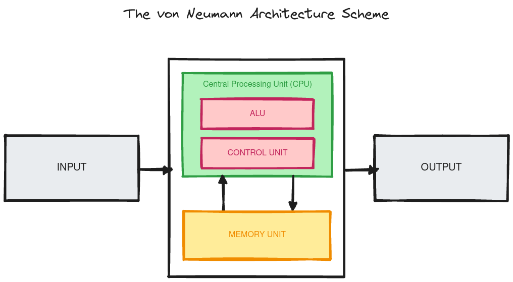
The von Neumann Model #
The von Neumann model is a computer model or architecture that is
widely used in many modern computer systems.
The model describes five (5) components for a computer:
Memory #
The component for storing the instructions or the data to be operated on.
The memory contains two (2) registers:
- Memory Address Register (MAR) for indexing or locating an address cell in the memory.
- Memory Data Register (MDR) for either loading or writing data from/to the indexed address cell by the MAR.
Processing Unit #
The component that operates on values, transforming them into other values.
The simplest processing unit in the von Neumann model is called the Arithemtic Logic Unit (ALU) and can do arithmetic and boolean operations.
The ALU processes a fix sized bit unit called a word whose length is dependent based on the design of the computer architecture.
ALUs are also accomodated with storage facilities called registers that are at close proximity to it and are used for temporary storage with submillisecond read/write speeds.
ALU registers are also uniquely identifiable and can be indexed ie. for bits there are uniquely identifiable registers.
Input/Output #
The input and output (or I/O) components are external devices or peripherals that allows the computer system to receive information and output it to something else.
An example of an input device could be a mouse or a keyboard.
For the output device it could be a monitor or a printer.
Control Unit #
This component manages which instruction is being executed or is going to be executed next by the processing unit.
The control unit contains two registers that does these things respectively and are the:
- Instruction Register (IR) stores the instruction currently being executed.
- Program Counter (PC) stores the address of the instruction that is going to be executed next.
Instruction Processing #
Instructions are the basic unit of computer processing and is made up of two components: the opcode and the operand.
There are fundamentally three (3) types of instructions that can be done in a computer system:
Operate #
Instructions that transform data into a different value in a computer system.
Examples of operate instructions are ADD, SUB, and AND.
Data Move #
Instructions that move data in different storage facilities such as in a register or a memory unit.
An example of a data move instruction is the LD or load instruction.
Control #
Instructions that changes how instructions are to be executed by the processing unit.
For example instead of sequentially executing instructions it can execute instructions in an arbitrary order.
These instructions are the basic building blocks for loops and branching statements in high-level programming languages.
An example of a control instruction is the BR or branch instruction.
The Instruction Cycle #
Instructions are processed in a processing unit in a systematic manner.
Typically processing units have a six (6) phase instruction cycle where each phase could perform or more steps in it.
Having steps means a phase is skipped for execution as an instruction might not necessarily need it.
FETCH #
The fetch phase in the instruction cycle does three (3) things:
- It first indexes the address cell in the memory unit by loading the value stored in the program counter (PC) to the MAR then increments the PC.
- The memory unit is then asked to load the contents of the indexed address cell into the MDR.
- The contents of the MDR are then loaded into the instruction register (IR) of the control unit.
DECODE #
The decode phase determines which action is going to be done by the processing unit as instructed from the IR in the control unit ie. should it do an operate, data move, or control instruction.
EVALUATE ADDRESS #
The evaluate address phase computes the memory location that is needed by the instruction process.
For example the LD instruction requires indexing of an address cell on
the memory unit for the data that is going to be moved.
It should be noted that not all instructions require this phase ie. for an operate instruction whose operands are in the ALU registers or within the instruction itself.
FETCH OPERANDS #
The fetch operands phase retrieves the source operands needed to process the instruction.
For example an LD instruction which fetches the data for its operand from
the memory unit or an ADD instruction which fetches the data for its
operands from the ALU registers or in its own instruction info.
EXECUTE #
The execute phase simply executes the given instruction.
STORE RESULT #
The store result final phase stores of the instruction into some storage facility such as the ALU registers or the memory unit.
Trap Instructions #
A trap (or interrupt) instruction is an instruction that halts (interrupts) a processor's current execution.
This is useful for processes that can be instructed to run indefinitely to be halted so it doesn't starve other processes.